
Heat Exchanger Test Stand Facility
Sandia National Laboratories’ Heat Exchanger Test Stand Facility can perform prototype 20- to 40-kilowatt heat exchanger performance analysis, and consists of multiple different particle, molten salt, CO2, air, and glycol flow loops for precise control of system pressures, densities, flow rates, and temperatures. Our test stand is ready to test and demonstrate the performance of your next generation heat exchanger technologies.
System Overview
The National Solar Thermal Test Facility features a versatile test stand designed for evaluating prototype heat exchangers within a high-temperature particle or molten salt circulation system. The system is supported by adaptable heat extraction and cooling loops.
Key features:
- Test area: 22” x 30” x 40” (L/D/H)
- Accommodates many types of heat exchangers: molten salt, particle, sCO2, and steam
- Vertical installation of test article
- Continuous, high-temperature particle loop
- Supercritical CO2 heat extraction system
- Flexible, mobile layout of subsystems to accommodate your needs
- Dry-cooling and chiller-coupled glycol extract heat with combined 60 kW thermal capacity
- Remotely controlled to ensure safety
- Operation requires trained Sandia staff members
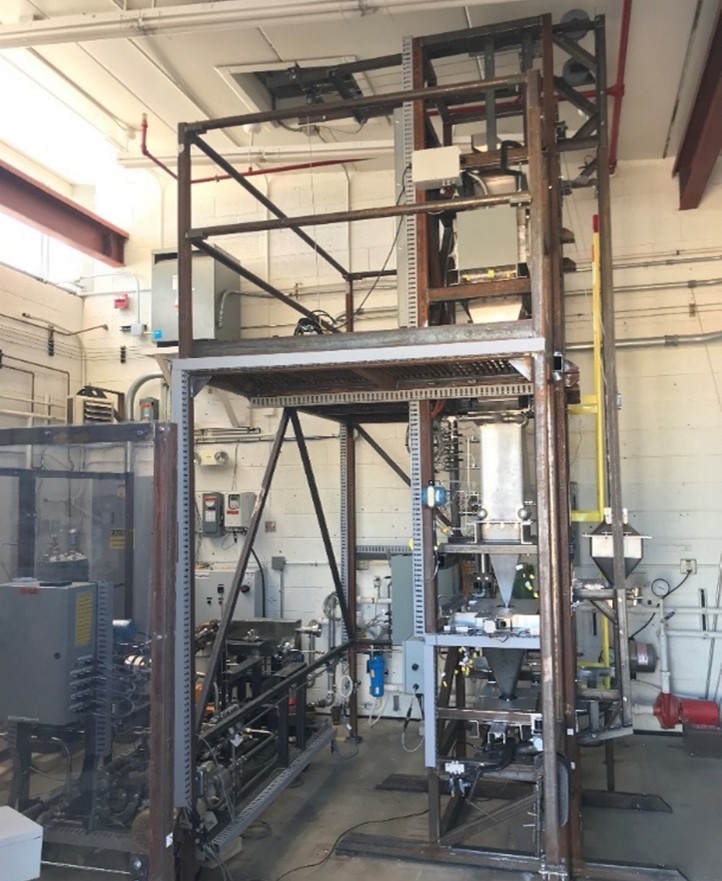


Heat Exchanger Test Stand. The test facility is split into two
separate rooms: a control room for all remote operations
and data acquisition, and the adjacent 350 ft2 test cell
containing the flow loops.
Test Your Heat Exchanger Using Our Facility
Sandia’s Heat Exchanger Test Stand (HX Stand) was funded by the U.S. Department of Energy and is available for use by external partners such as private industry and technology developers, universities, equipment manufacturers, government agencies, and national laboratories. For a complete system overview and breakdown of components, specifications, and procedures, read our Heat Exchanger Stand Brochure.
Operating Conditions
Actual test conditions vary by heat exchange design and accompanying equipment such as inlet and outlet hardware, flow control mechanisms, pressure ratings. However, Sandia’s Heat Exchanger Test Stand can accommodate the following conditions:
| Aspect | sCO2 Loop | Particle Loop | Air Supply | Glycol (Loop 1) | Glycol (Loop 2) |
|---|---|---|---|---|---|
| Flow Rate | 0-250 g/s | 0-250 g/s | 0-1000 slpm | 0-10 gpm | 0-10 gpm |
| Supply Temperature Range | 30-575 °C | 25-775 °C | 0-400 °C | 20-50 °C | 15 – 50 °C |
| Pressure Range | 1160 – 2500 psig (8-17.2 MPa) | N/A | 0 – 130 psig (0-0.9 MPa) | 0 – 30 psig (0-0.2 MPa) | 0 – 30 psig (0-0.2 MPa) |
Components
The table below summarizes the parameters, design attributes, and operating conditions for heat exchangers that can be supported by the heat exchanger test stand. Together, these parameters define the operating range and integration capabilities of the test stand for evaluation of heat exchanger performance.
| Parameter | Supercritical CO2 Loop | Particle Loop | Salt Loop |
|---|---|---|---|
| Heat Exchanger Inlet Temperature Range | 30-575 °C | 25-775 °C | 300-775 °C (salt chemistry dependent) |
| Heat Exchanger Outlet Temperature Range | 30-700 °C | 25-700 °C | 300-775 °C (salt chemistry dependent) |
| Operating Pressure | 1160 – 2500 psig (8-17.2 MPa) | Atmospheric | 0-110 psig (0-0.75 MPa) |
| Flow Rate | 0-250 g/s | 0-250 g/s | 0-2000 g/s |
| Density Range | 850 -960 kg/m3 | N/A, dependent on particle bulk | 1000-2000 kg/m3, dependent on salt chemistry |
| Heating | 20 kW electric heating, or recovery of carried sCO2 heat via recuperation | 60 kW electric heating | 20 kW electric heating |
| Supported Fluids/Heat Transfer Media | Liquid CO2 from siphon tube bottles or dewar, pressurized to supercritical | Sintered bauxite, engineered oxides, additional materials possible upon request | Variety of salt chemistries including FLiNaK and NaCl-KCl-MgCl2 |
The sCO2 loop is instrumented for measuring temperature, pressure, differential pressure, density, and mass flow rates.
| Aspect | Details |
|---|---|
| Pressure and Temperature | Measured in all piping segments and at: recuperator, heater, fill system, pump, heat exchanger |
| Pressure Change | Monitored across heat exchanger with differential and steady state pressure transducers |
| Temperature | Direct sCO2 temperatures measured with RTDs inside piping/tubing; external surface temperatures with thermocouples (TCs) |
| Flow and Density | Two Coriolis flow meters at pump outlet: one for cold loop flow, one for hot loop and heat exchanger flow |
| Particle Loop | Two Coriolis flow meters at pump outlet: one for cold loop flow, one for hot loop and heat exchanger flow |
| Data Collection | Over 100 temperature points monitored and are adjustable per test; inlet/outlet temps of all major components collected; data monitored from control room; exportable to Excel and text files |
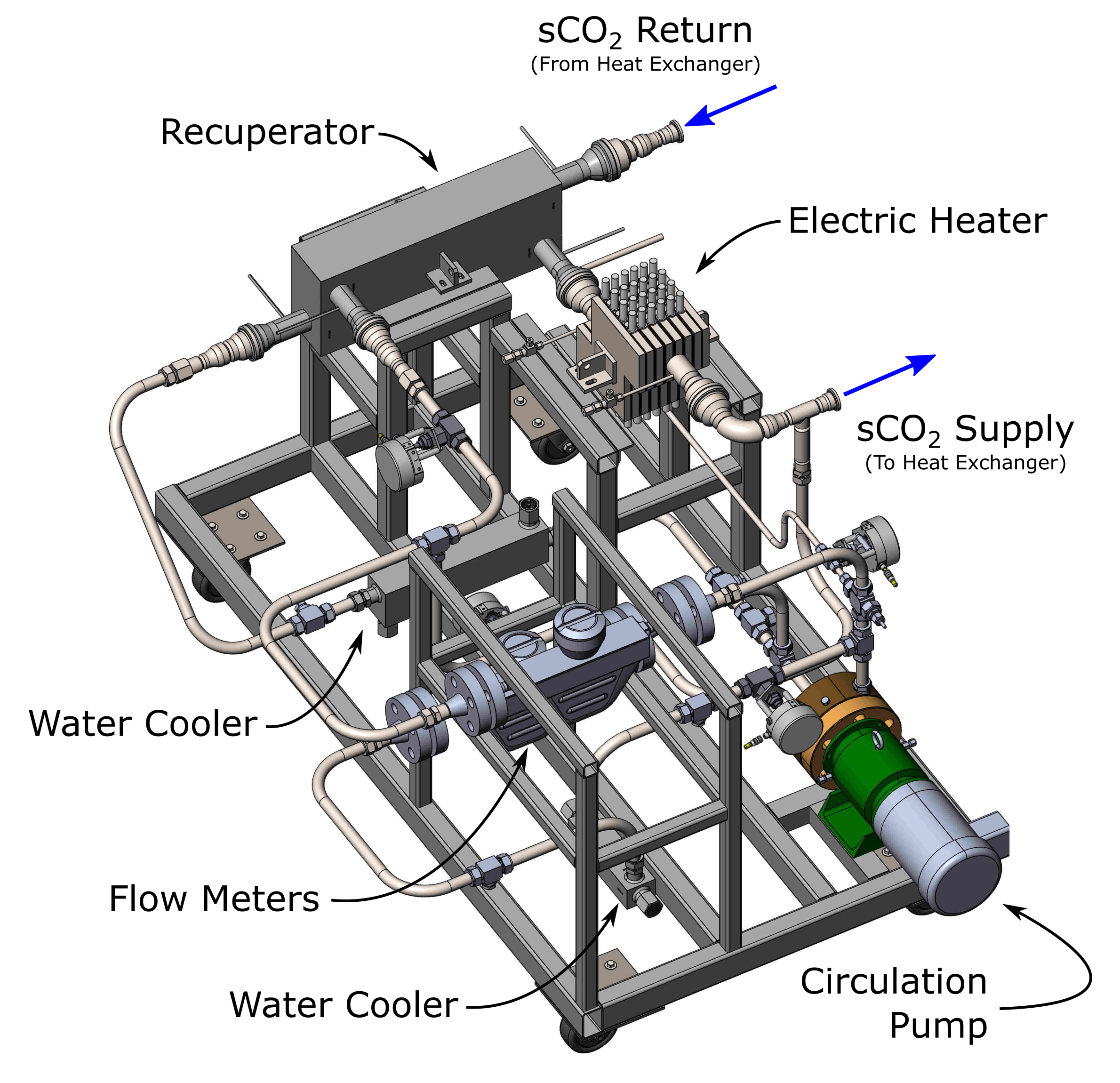
Sandia’s 575°C sCO2 Loop
CAD Visualization
The particle loop is designed for circulation of granular media or particles.
- Carbo HSP 40/70 particles are standard in this loop, though many types and sizes are supported
- 60-kilowatt heater provides heat exchanger inlet temperatures up to 775 °C
- Flow rates up to 250 grams per second
- Slid-gate style valve on a linear actuator controls particle flow rate
- Flow rates from 0 to 300 grams per second are supported
- Steady state flow over long duration tests is most reliable from 50 and 250 grams per second
- Skip hoist supports recirculation of particles due to higher operating temperature capabilities, and particle size and material flexibility
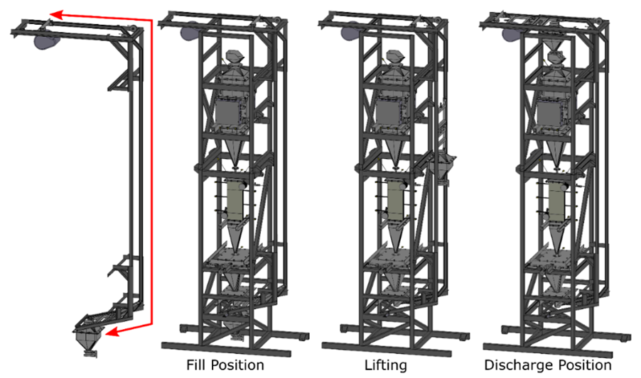
Particle skip hoist fill, lifting, and discharging positions. The skip hoist can be manually or automatically triggered to carry particles from the bottom of the particle loop to the heater at the top. Dwell time for discharging can be custom programmed by the user to accommodate different skip inventories and flow changes from particle sizes.
sCO2 Loop Instrumentation
| Aspect | Details |
|---|---|
| Pressure and Temperature | Measures temperature, pressure, differential pressure, density, and mass flow rates. Measured in all piping segments and at: recuperator, heater, fill system, pump, heat exchanger |
| Pressure Change Monitoring | Across heat exchanger with differential and steady state pressure transducers |
| Temperature Measurement | Direct sCO2 temperatures inside piping/tubing with RTDs; external surface temperatures with thermocouples (TCs) |
| Flow and Density Measurement | Two Coriolis flow meters at pump outlet: one for cold loop flow, one for hot loop and heat exchanger flow |
Particle Loop Instrumentation
| Aspect | Details |
|---|---|
| Instrumentation Components | Weigh hopper for particle flow rate measurement |
| Temperature Measurement | Thermocouples at heater, heater outlet, heat exchanger inlet, multiple points across heat exchanger, heat exchanger outlet, and weigh hopper |
Data Collection
| Aspect | Details |
|---|---|
| Temperature Monitoring | Over 100 temperature points monitored and are adjustable based on test requirements |
| Component Monitoring | Data monitored from adjacent control room; exportable to Excel spreadsheets and text files |
Heat exchangers are typically mounted on support frames custom-built at Sandia and then integrated into the test stand. Sufficient length for the outlet hopper should be considered to meet flow requirements of a specific unit. Typical heat exchanger installations are 20 to 25 inches tall, with 15 to 20 inches for hoppers, though hoppers can be as short as a few inches tall, so long as the height accommodates desired flow requirements.
A 22-by-30-by-40-inch (length/depth/height) test area is available for heat exchanger prototypes, including the inlet and outlet hoppers.
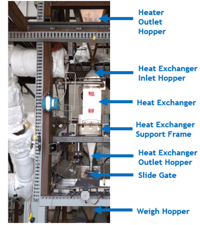
The Heat Exchanger installation
within the test stand.
Resources
Contact
Dimitri Madden, Principal Investigator
damadde@sandia.gov
Margaret Gordon, Manager, Solar Thermal Technologies
megord@sandia.gov